This tutorial demonstrates how we determine the voltage and ampere values in a parralel circuit under Ohm’s and Kirchhoff’s laws using Polytech’s SMART:Blox S5 STEM Set with ARD:icon block programming.
Equipment
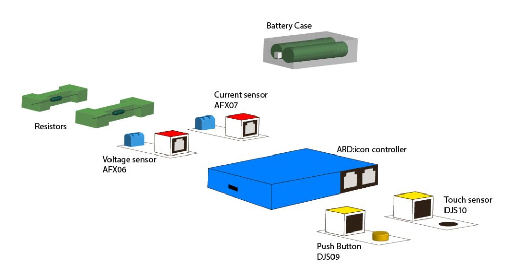
- Hardware
- SMART:Blox S5 STEM Set
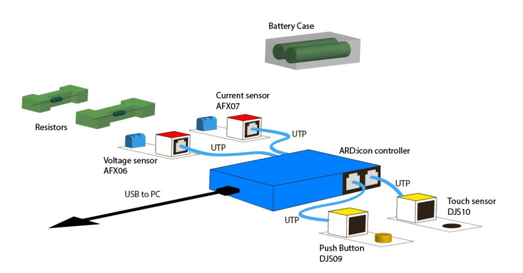
- ARD:icon controller
- Voltage sensor AFX06
- Current sensor AFX07
- Touch sensor DJS10
- Push Button DJS09
- UTP cables (x4)
- USB cable
- White bricks (x8)
- Blue bricks (x4)
- Green bricks (x2)
- Bricks base
- AAA Batteries (x2)
- Battery case
- Resistors (x2)
- Cirquit connection wires (x8)
- SMART:Blox S5 STEM Set
- Software
- Polytech ARD:icon application on a Windows PC
Resources

Safety Notes
There are no special safety requirements for this experiment.
1. Introduction
In a parallel circuit, all components are connected across the same two points, so each component gets the full voltage of the source. If one component fails (open circuit), the others will continue to operate.
Basic Components
- Resistor (R): Each resistor offers a path for current flow.
- Voltage Source (V): Provides electrical potential energy across all branches.
- Current (I): The flow of electric charge through each branch.
Characteristics of a Parallel Circuit
Same voltage is applied across each component in parallel.
Total current is the sum of the currents through each resistor: 𝐼total=𝐼1+𝐼2+⋯⋯+𝐼𝑛
Total resistance in a parallel circuit is less than the smallest individual resistance. The reciprocal formula is used:
Ohm’s Law is a fundamental relationship between voltage (V), current (I), and resistance (R):
𝑉=𝐼×𝑅
Where:
- V is the voltage (Volts)
- I is the current (Amperes)
- R is the resistance (Ohms)
Applying Ohm’s Law in parallel circuits
- The voltage across each resistor is the same as the total voltage supplied by the source.
- The current is divided among the branches, and each branch carries a current proportional to its resistance
Power (P) is the rate at which energy is used or dissipated in a circuit. It’s measured in watts (W).
Power Formula: 𝑃=𝐼2×𝑅
Where:
- P is power (Watts)
- I is the current (Amps)
- R is the resistance (Ohms)
Alternatively, using Ohm’s Law, you can express power as: 𝑃=𝑉2∕𝑅 or 𝑃=𝑉 x 𝐼
In this session, you will use the voltage and current sensor to calculate the resistance and power of the circuit. You will also use the push button and the touch sensor. Using these sensors, you will program your circuit so that:
- IF you push the push button THEN the controller will print the resistance of the circuit to the terminal.
- IF you touch the touch sensor THEN the controller will print the power of the circuit to the terminal.
2. Setup Instructions
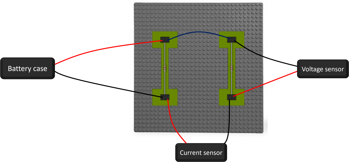
- Encapsulate all 4 Electronic devices – each one separetely – to the blocks to create 4 EB:blocks

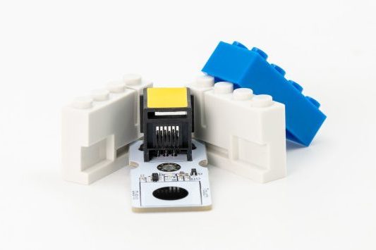
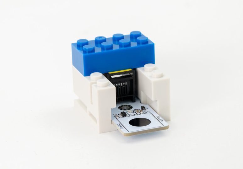
- Encapsulate each of the two Resistors to the green Resistor block to create 2 resistor blocks

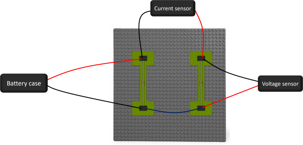
- Use the blocks base to secure the EB:blocks and Resistor blocks in a setup as the one in the photos:
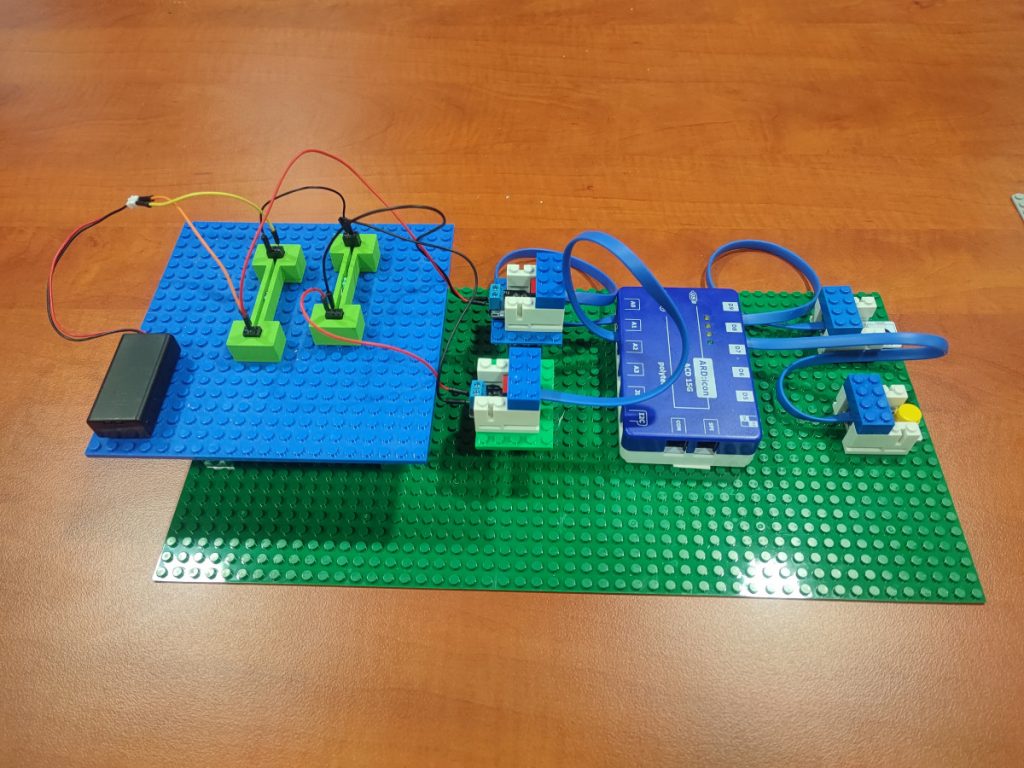
3. Connections
In this session, you will use the voltage and current sensor to compare how voltage and current behave differently in serial and parallel circuits.
- Connect the Current sensor AFX07 to ARD:icon analog port 0 (A0).
- Connect the Voltage sensor AFX06 to ARD:icon analog port 1 (A1).
- Connect the Touch sensor DJS10 to ARD:icon digital port 9 (D9).
- Connect the Push Button DJS09 to ARD:icon digital port 8 (D8).
- Connect the ARD:icon controller to your PC using the USB cable

4. Programming

This section is divided in two parts.
- Part 1: By using the voltage and ampere sensors you will apply the Ohm’s law by measuring the voltage and ampere of knob 1 and knob 2 and then calculate the resistance of each knob. You will use the ARD:icon to program the circuit to print these values. First you will measure by using the set up of knob 1 and then of knob 2.
- Part 2: At part 2 by using the ARD:icon software you will measure the total current, resistance and power of the circuit. Once you have uploaded the code to the ARD:icon controller and open the terminal, you have to connect the Circuit 1. Touch the touch sensor one time to take the measurement for knob 1. Then connect the circuit 2 and push continuously the push button and see the results that are printed to the terminal screen.
4.1. Part 1
Run the ARD:icon application and select “Start”.
4.1.1. ARD:icon Programming
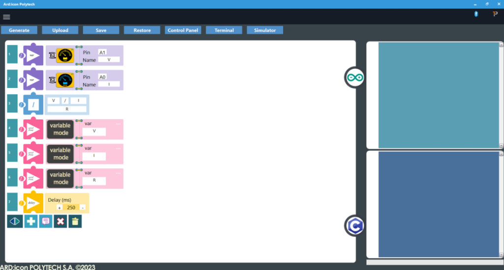
Read Values from Sensors
- Create a new block command by pressing the + button
- Select the Voltage sensor AFX06.
- Assing vales to the block: Pin A1 and Name V.
- Create a new block command by pressing the + button
- Select the Current sensor AFX07.
- Assing vales to the block: Pin A0 and Name I.
Calculate Resistance
- Create a new block command by pressing the + button
- Select Division (/) from the Math menu.
- Assign values: V/I and name R the division result.
Display Values
- Create a new block command by pressing the + button
- Select Serial Print .
- Click on the … icon to change to Variable Mode.
- Assign value V to var.
- Create a new block command by pressing the + button
- Select Serial Print.
- Click on the … icon to change to Variable Mode.
- Assign value I to var.
- Create a new block command by pressing the + button
- Select Serial Print.
- Click on the … icon to change to Variable Mode.
- Assign value R to var.
- Create a new block command by pressing the + button
- Select Delay Time.
- Set delay value to 250 ms.
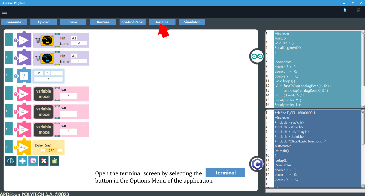
When finished the block code will look like this:
- Press Generate to generate the programm code

- Press Upload to upload the generated code to the ARD:icon controller

- When the uploading is Done press OK to the prompt

- Press Terminal to open the ARD:icon Terminal Window
- Connect the Power-Resistors Circuit 1 according to the image:
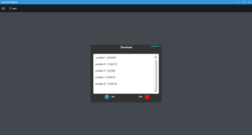
- On the Terminal window click ON to start printing the values to the terminal. Wait a few seconds and
- On the Terminal window click OFF to stop printing the values to the terminal
- Connect the circuit-Resistors Circuit 2 according to the image:

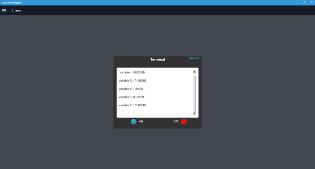
- On the Terminal window click ON to start printing the values to the terminal. Wait a few seconds and
- On the Terminal window click OFF to stop printing the values to the terminal
4.2. Part 2
Run the ARD:icon application and select “Start”.
4.2.1. ARD:icon Programming
Programming “Touch the touch sensor to Measure the Voltage of the Circuit 1 upper Node”
- Create a new block command by pressing the + button
- Select the if statement
- Select the Touch sensor DJS10 High state.
- Assing vale to the block: Pin D9.
- Press the <> to indent next line
- Create a new block command by pressing the + button
- Select Math > var
- Select the Current sensor AFX07 High state.
- Assign the values to the block: Pin A0, Name I1.
- Press the <> to unindent next line
Programming “Push the push button to Measure the Voltage of the Circuit 2 lower Node, Calculate and Print Values”
- Create a new block command by pressing the + button
- Select the if statement
- Select the Push Button DJS09 High state.
- Assing vale to the block: Pin D8.
- Press the <> to indent next line
- Create a new block command by pressing the + button
- Select Math > var
- Select the Current sensor AFX07 High state.
- Assign value to the block: Pin A0, Name I2.
- Create a new block command by pressing the + button
- Select Math > var
- Select the Voltage sensor AFX06 High state.
- Assign value to the block: Pin A1, Name V.
- Create a new block command by pressing the + button
- Select Math > Addition
- Assign value to the block: I1 + I2 Name I
- Create a new block command by pressing the + button
- Select Math > Division
- Assign value to the block: V / I Name R
- Create a new block command by pressing the + button
- Select Math > Multiplication.
- Assign value to the block: V * I Name P
- Create a new block command by pressing the + button
- Select Serial Print
- Click the … to switch to Variable mode
- Assign value to the block: I
- Create a new block command by pressing the + button
- Select Serial Print
- Click the … to switch to Variable mode
- Assign value to the block: R
- Create a new block command by pressing the + button
- Select Serial Print
- Click the … to switch to Variable mode
- Assign value to the block: P
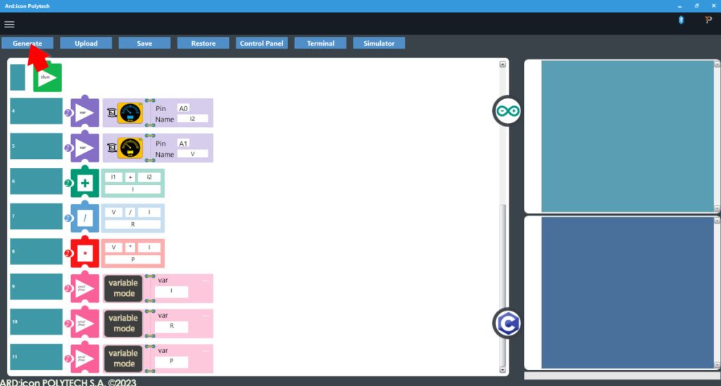
When finished the block code will look like this:

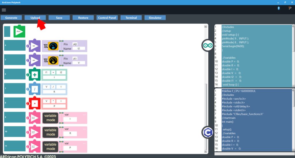
- Press Generate to generate the programm code
- Press Upload to upload the generated code to the ARD:icon controller
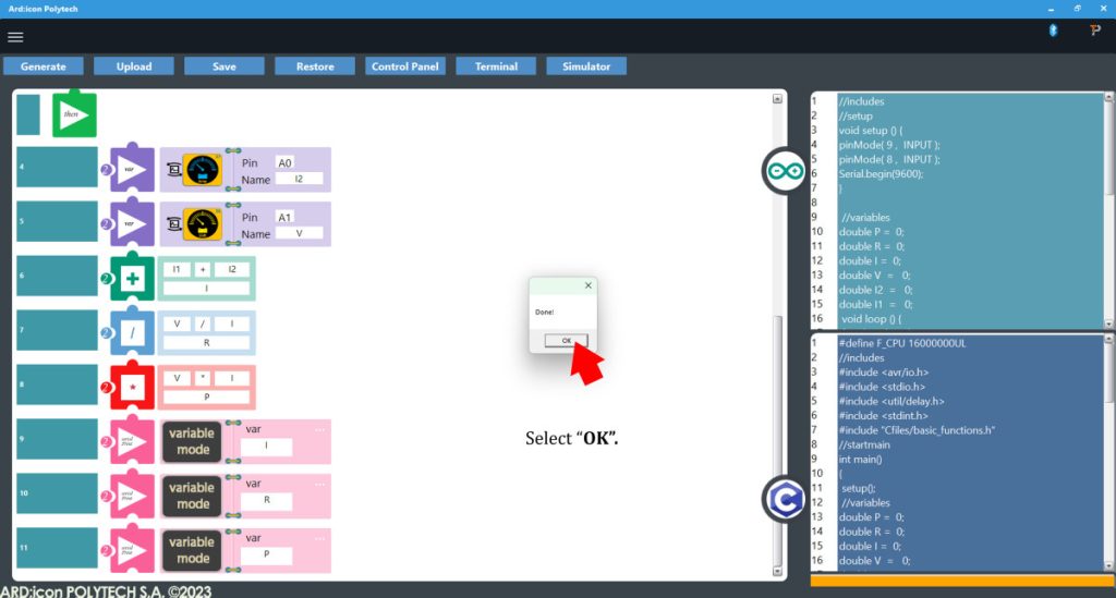
- When the uploading is Done press OK to the prompt
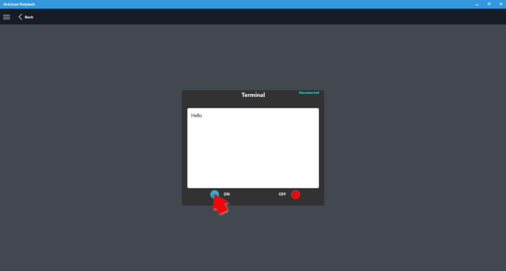
- Press Terminal to open the ARD:icon Terminal Window

- Connect the Power-Resistors Circuit 1 according to the image:
- On the Terminal window click ON.
- Touch the touch sensor one time to get the reading
- On the Terminal window click OFF to stop printing the values to the terminal
- Connect the circuit-Resistors Circuit 2 according to the image:
- On the Terminal window click ON
- Push the push button continuously to record the values
- On the Terminal window click OFF to stop printing the values to the terminal
End of tutorial