Course Contents
1. Circuit Components
An electric circuit is formed when a conductive path is created allowing the free electrons of a source to constantly move around the conductor and elements related to him.
The serial and parallel arrangements of circuits are common for the study of electricity and electronics.
When the elements are connected in series, they are connected along a single path so that the current flowing through all the components to have the same intensity.
When the elements are connected in parallel , they are connected along a single path so that the voltage flowing through all the components.
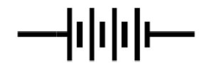
The element is a chemical source of electricity.
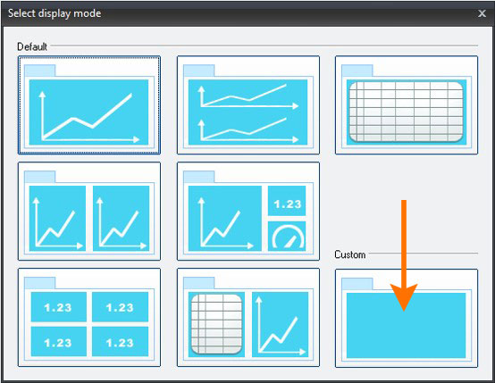
By adding multiple elements a battery is constructed.
Depending on the chemical reaction a battery can have different voltage values. The most common batteries have a voltage value of about 1,5 V per chemical element. Also, according to their size they are categorized as ΑΑ, ΑΑΑ, C, D etc.
Two important parameters of an element is the electromotive force (EMF) or the nominal voltage and capacity.
The electromotive force measured in volt, is the power that moves the electrons around the circuit.
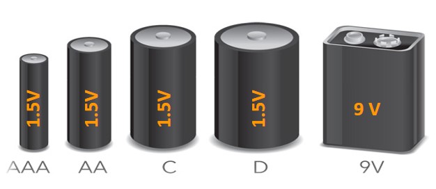
The capacity is a measure of the total quantity of electricity stored in the element. Measured in ampere-hours (Ah) or miliamperoria (mAh).
| Battery Type | Capacity in mAh |
|---|---|
| D | 12000 |
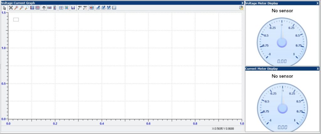
| C | 6000 |
| AA | 2000 |
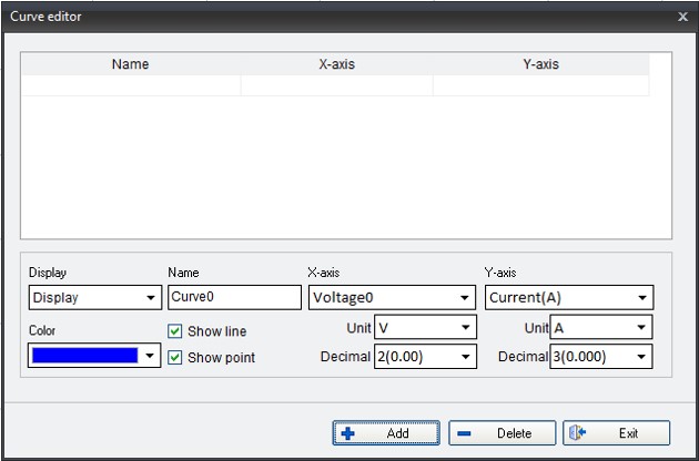
| AAA | 1000 |
| PP3 (9 V) | 500 |
If you have an element of 3 Ah, providing 0.1 A current in a circuit, then this element will have a lifetime 30 hours.
Question 1
The role of the electrical source in a circuit is:
- to produce electric charges
- to create potential difference
- to generate energy from scratch
- to convert electrical energy to chemical
1.1. Serial Arrangement
In serial circuits the current passing through all the elements has the same intensity. The elements are positioned adjacent to one another in series.
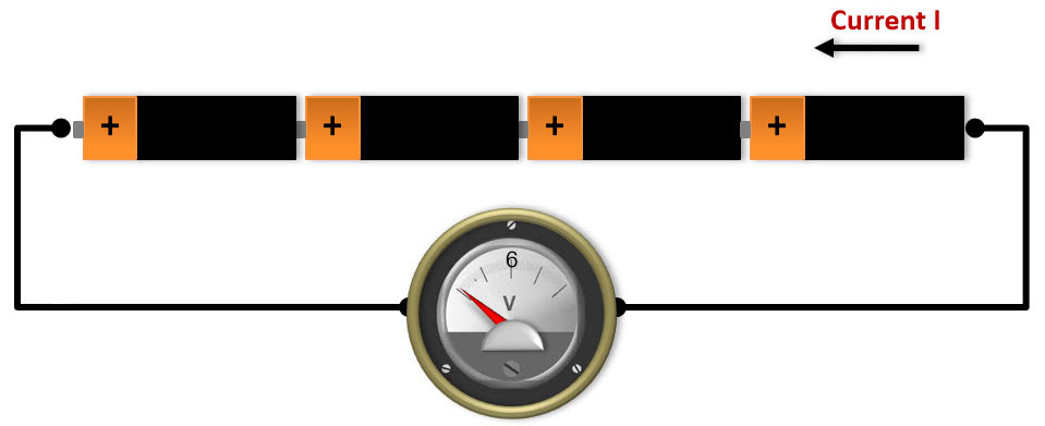
If four elements with 1,5V EMF each are connected in series then a battery of 6V EMF is created (4*1.5V).
This arrangement has the sum of the EMFs of all elements but provides the same power as a single element.
The schematic of this arrangement is represented as follows:
1.2. Parallel Arrangement
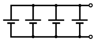
If four elements of 1.5 V are arranged in parallel, a 1.5 V battery is created, but it can provide up to four times of each element’s current intensity.
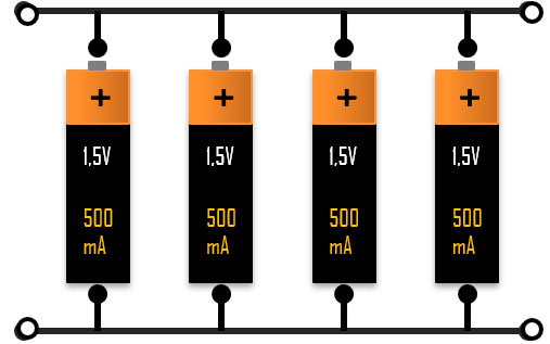
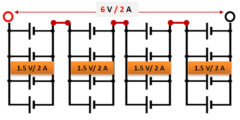
If the power provided by each element is 0,5 Amps (500 mA), then this arrangement can create a battery of 1.5 V and 2 Amps (4 x 0.5 = 2).
So, now a battery cell with these characteristics is created. If you use it as an element you can have a battery that can supply current of 6 Volts and 2 amps. How? By adding this element of high amperage and low voltage element in series with 3 similar elements.
Question 2
When two electric sources of (Ε1 , r1 ) and (E2 , r2 ) are connected in series, then the resulting arrangement is equivalent to an electrical source of:
- Ε = 2Ε and r = 2r
- Ε = Ε and r = 2r
- Ε = 2Ε and r = r
- Ε = Ε and r = r/2
Question 3
When two electric sources of (Ε1, r1) and (E2, r2) are connected in parallel, then the resulting arrangement is equivalent to an electrical source of:
- Ε= Ε1 + Ε2 and r= r1 – r2
- Ε= Ε1 + Ε2 and r= r1 + r2
- Ε= Ε1 – Ε2 and r= r1 – r2
- Ε= Ε1 + Ε2 and r= r1 / r2
2. Circuit Resistors
2.1. Resistors in Series
Let now examine the parallel and series arrangement of resistors.
If two resistors of 2 kΩ are connected in series with an elements of 3 V, what can you calculate according to the schematic?
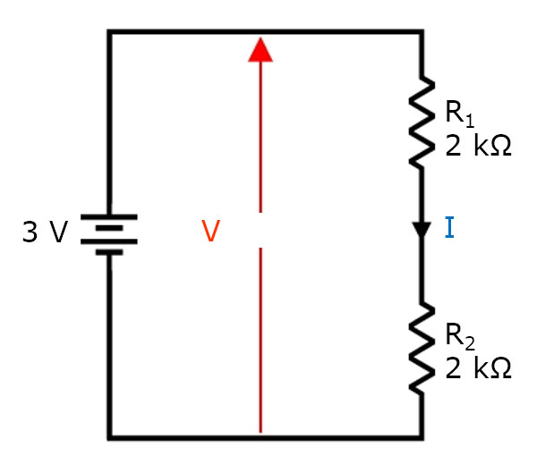
You know that the current passing through the circuit has the same amperage in all points of the circuit.
The voltage across each resistor should be the same, since each resistor has the same resistance and the same current flows through it.
The EMF source is the battery element of 3V. Therefore, each resistor will have a potential difference of 1.5 V across its length.
Provided that:
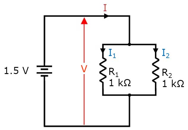
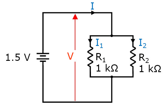
2.2. Resistors in Parallel
Now, let’s connect two resistors of 2 ΚΩ in parallel with an element, according to the schematic:
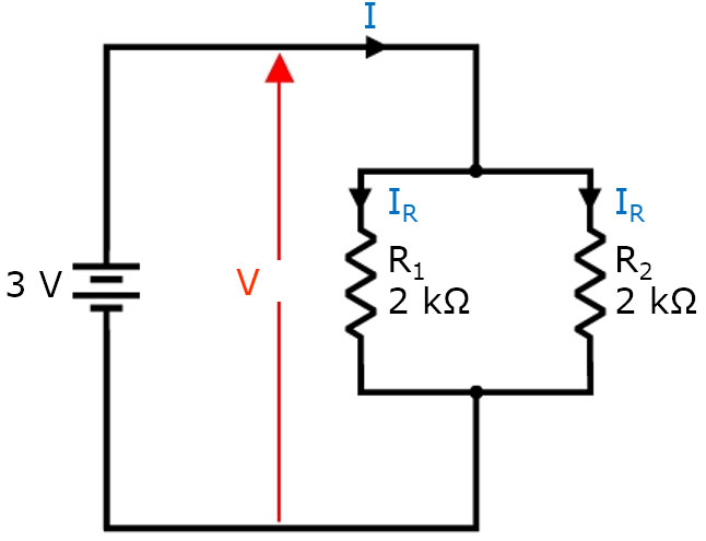
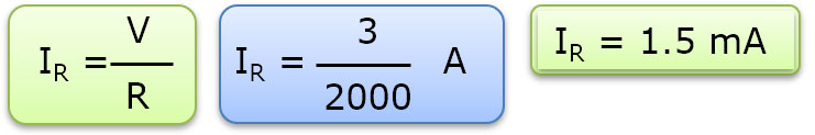
Each resistor will have voltage value of 3V across its length. But which will the current intensity of each resistor be?
The total current of each element will be 2 × IR, which is 3 mA.
2.3. Resistance of Resistors in Series or Parallel
You saw that that the intensity of the current is different in serial and parallel circuits, even when the same elements are used.
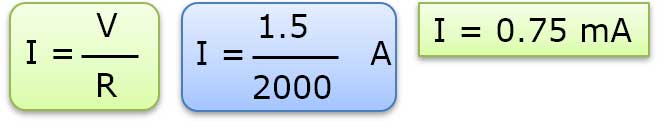
If there is only one resistor of 1 kΩ that is connected with a battery 1.5 V, then the current is of 1,5 mA.
If the resistors are connected in series, the current is reduced by half, 0.75 mA. This implies that the total resistance of the circuit should be doubled.
If the resistors are connected parallel the current doubles to 3 mA. This implies that the total resistance should be reduced by half.
In the following example the circuit is simplified since there are only two resistors with the same resistance value, so it is easy to calculate the current passing through the resistors.

When the circuits are more complex, the resistors are not of the same value, more general equations are needed that will allow to find the total resistance of the circuit, regardless of the resistor values.
Question 4
If two resistors of R1 and R2 (R1 R2) are connected in series:
- They have the same voltage at their edges
- The same current passes through them
- consume the same electric power per unit time
- their equivalent resistance R results from the relationship 1/R=1/R1+1/R2
Question 5
When two resistors of R1 and R2 (R1 R2) are connected in parallel:
- They have the same voltage at their edges
- The same current passes through them
- consume the same electric power per unit time
- their equivalent resistance R results from the relationship R = R1+R2
3. Kirchhoff’s Laws
Kirchhoff’s circuit laws are two equalities that deal with the current and potential difference (commonly known as voltage) in the lumped element model of electrical circuits.

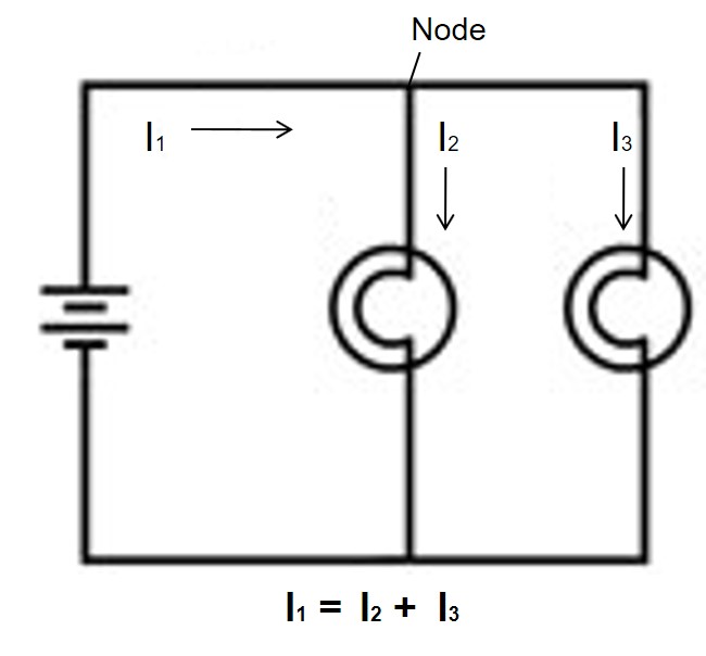
In an electric circuit Node is called the point of the circuit, where at least three conductors are met .

Loop is called the part of the circuit between two nodes.
Each closed circuit is called loop.

3.1. Kirchhoff’s first law, Kirchhoff’s point rule, or Kirchhoff’s junction rule (or nodal rule).
At any node (junction) in an electrical circuit, the sum of currents flowing into that node is equal to the sum of currents flowing out of that node.

Σ(Ii) = Σ(Io)
If you consider the Ii is positive and Io is negative then the first rule of Kirchhoff can be expressed as:
The algebraic sum of currents in a network of conductors meeting at a point is zero.
Σ(I) = 0
3.2. Kirchhoff’s voltage law
The directed sum of the electrical potential differences (voltage) around any closed network is zero.
Σ(ΔV) = 0

Question 6
According to Kirchoff’s second law:
- Along a closed circuit the algebraic sum of the potential differences is equal to zero
- In a closed circuit, the algebraic sum of the currents is equal to zero
- The energy a circuit absorbs is equal to zero
- The charge of the circuit is equal to zero
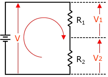
3.3. Resistors in Series
Three resistors of R1, R2 and R3,are connected in series with a battery EMF V.
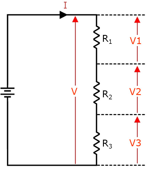
The R1 voltage is V1, the R2 voltage is V2 and the R3 voltage is V3.
According to Kirchhoff’s voltage law:
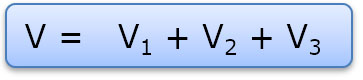
The same current, Ι, passes through all resistors. By replacing V with IR:
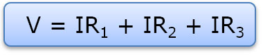
Simplifying gives:
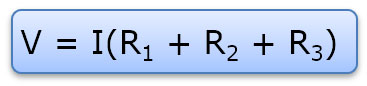
Therefore:
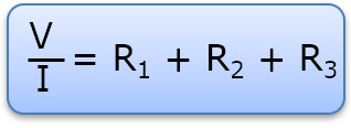
V/Ι can be replaced by the RT, where RT is the equivalent total resistance of the three resistors:

So the resistors in series can be replaced by a resistor with a resistance which is equal to the sum of their individual values.
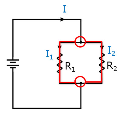
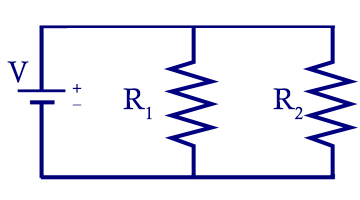
3.4. Resistors in Parallel
Three resistors of R1, R2 and R3,are connected in parallel with a battery EMF V.
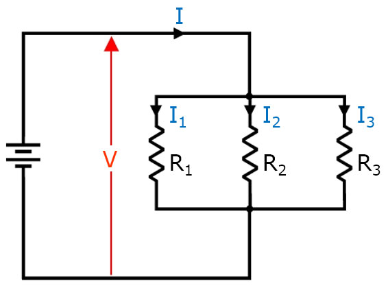
The voltage across each resistor is V.
The R1 current intensity is Ι1, the R2 current intensity is Ι2, and the R3 current intensity is Ι3.
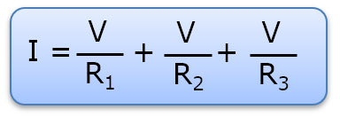
According to Kirchhoff’s junction rule (or nodal rule):

By replacing Ι with V/R then:
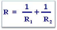
3.4.1. Resistors in Parallel – Equivalence
Simplifying gives:

Therefore:
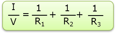
Ι/V can be replaced by 1/RT, where RT is the equivalent total resistance of the three resistors:

3.5. Resistors in Series And In Parallel
If the circuits containing resistors in series and parallel can be simplified by:
- By replacing the parallel resistors with their equivalent resistor.
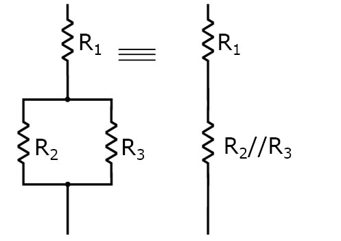
- By replacing any of the resistors in series with the equivalent resistor.
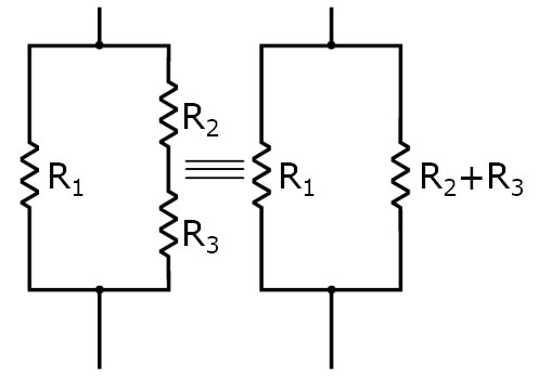
When the resistors are in series, the equivalent resistance is always higher than the largest resistor.
When the resistors are in parallel, the equivalent resistance is always lower than the smallest resistor.
Question 7
Which is the total resistance of the circuit below:

- 2R/3
- R
- 5R/11
- 3R/2
Experiments
Experiment 1/3: Construction Of Serial And Parallel Circuits
Equipment
- PS2031.1 Electric board 1
- PS2031.3 Battery holder variable
- PS2031.4 Banana clips cables x6
- PS2031.5 Mini lamps
Materials
- 4 C type batteries (1.5 V each)

Safety Note
There are no special safety requirements for this experiment.
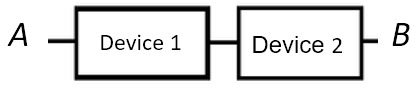
Electrical Circuit: is an interconnection
(α) sources
(b) Consumer (ohmic resistors)
(c) Switches and capacitors that are connected by conductive wires of negligible resistance
Direct current (DC) is the unidirectional flow of electric charge. The electric current flows in a constant direction, particular circuit voltage or current does not depend on the past value of any circuit voltage or current.
There are two types of circuits:
In series, Components connected in series are connected along a single path, so the same current flows through all of the components
In parallel, Components are connected so the same voltage is applied to each component

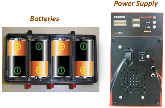
Each integrated circuit requires a power source. For our experiments we will use either the power supply of the mobile laboratory or batteries.
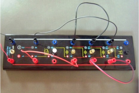
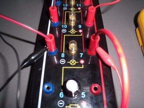
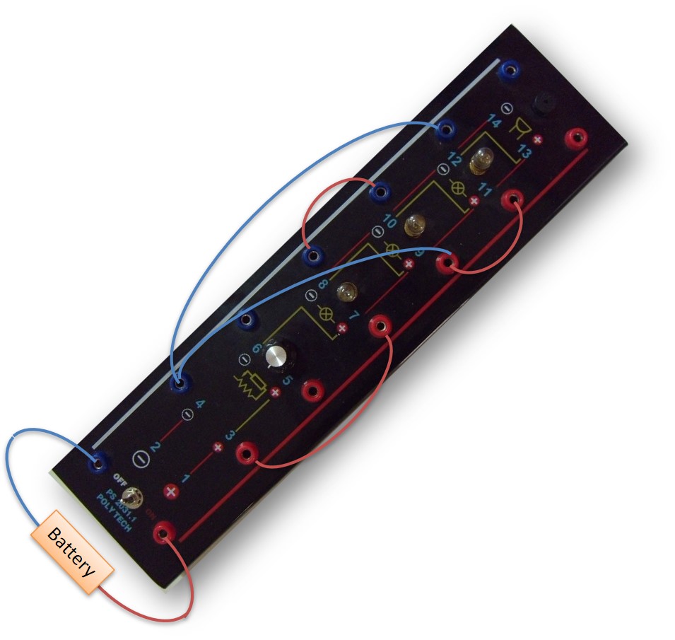
Action: With the cables of the batteries or of the power supply connect the positive pole (red) to the port 1 of the electric board 1 and the negative pole (black) to the port 2 of the electric board.

Action: Close the circuit by using 2 banana clip cables. Connect one from port 3 to 7 and the other from port 4 to 8. See the picture.

Action: Turn on the switch.
Effect: If the lamp turns on, then your circuit is successfully connected.
Create a circuit of two lamps in series.

In the same way create a circuit of 3 lamps in series.
Action: Remove a lamp and check if the current flows through the circuit.
Effect: By disconnecting a lamp the circuit is not closed so the current does not flow through it.
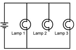
Create a circuit of two lamps in parallel.

In the same way create a circuit of three lamps in parallel.

Action: Remove a lamp and check if the current flows through the circuit.
Effect: This time the disconnection of a lamp does not affects the other lamps. The circuit remains closed and the rest lamps are on.
Question 1
Three resistors of 2Ω, 3Ω and 4Ω are connected so that the total resistance to be equal with 9 ohms. The resistors are connected
- in series
- in parallel
- the 2Ω and 3Ω resistors are in parallel and the 4Ω resistor in series
- the 2Ω and 3Ω resistors are in series and the 4Ω resistor in parallel
Question 2
To measure the intensity of the current flowing through a consumer and the voltage applied at its ends, are connected
- the ammeter in parallel and the voltmeter in series.
- both devices in series
- both devices in parallel
- the ammeter in series and the voltmeter in parallel
Question 3
In a simple closed circuit (source , switch, lamp): The energy that is transferred to the ions of the cable of each electron that moves from one end of the lamp to the other, is proportional to the voltage applied to its ends.
- True
- False
Question 4
In a series circuit, according to the Ohm’s Law, the current that passes through the circuit is I=V/Rtot where V is the voltage applied at the poles of the source.
- True
- False
Experiment 2/3: Kirchhoff’s first law
Equipment
- PS2031.1 Electric board 1
- PT2013.3 Battery holder variable
- PT2013.10 Cable banana clips and cable alligator clips
- PCB1001.25 Digital multimeter
Materials
- 4 C type batteries (1.5 V each)
Safety Note
No personal safety requirements for this experiment.
The device we need to measure electric current in a circuit is called an ammeter. The digital multimeter can be set to act as an ammeter, in this experiment we will set it for direct current of up to 10 amps.
Tip: Always remember that an ammeter has to be in series in a circuit, and for that reason it’s resistance is minimal in order to not affect the current.
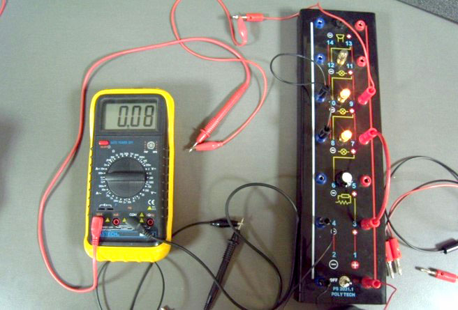
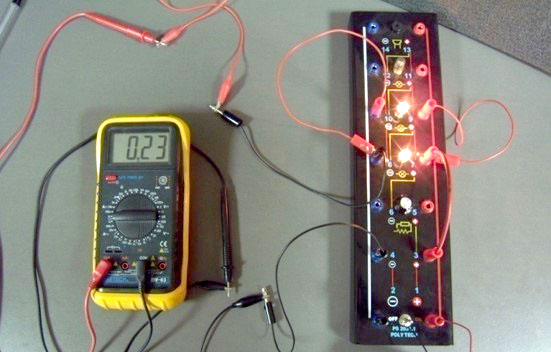
Let’s create our first circuit by connecting 4 batteries (6V) and a lamp.

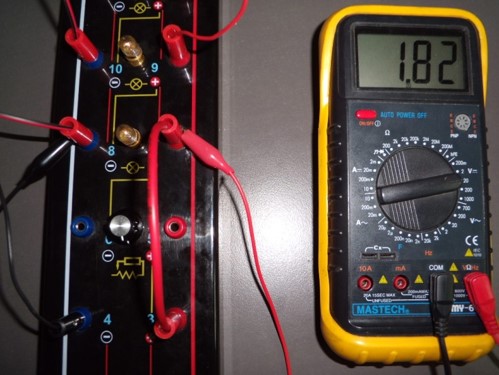
Action: Measure the electric curren before the lamp. Keep note of your measurement as we will also use it later.
Action: Measure the electric current after the lamp as in previous image.
Effect: We can notice that the electric current doesn’t change, it is constant for the whole circuit.
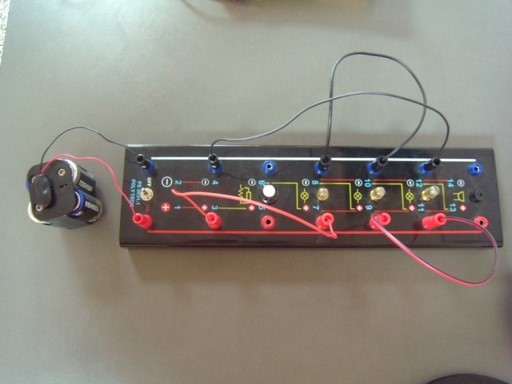
Connect a second lamp in series and measure again the electric current.
Connect a third lamp in series and measure again the electric current.
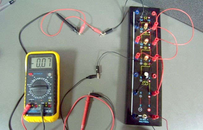
Note: If the ammeter is connected with reversed probes as in photo, then it will display with a minus sign the correct direction of current.
When we created circuits with extra lamps we noticed that the glowing was smaller. This is because the resistance in our circuit got increased and as a result the electric current got reduced.
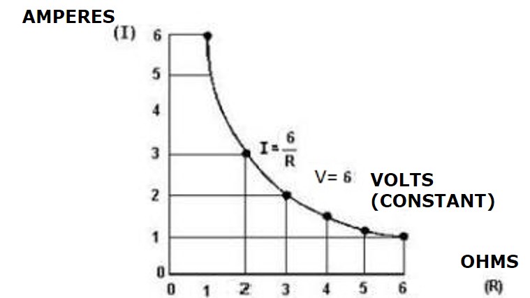
Besides our results this is easily explained with Ohm’s law. Ohm’s law states that the electrical current (I) flowing in an circuit is proportional to the voltage (V) and inversely proportional to the resistance (R).
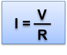
The voltage in all our circuits was the same, as we had the same power source in every occasion.
So now that we know our current (I) and voltage (V) in every occasion we can calculate the resistance (R) and make a graph between R and I.
Note: We are talking about the sum of the resistance (R) for the whole circuit.
There is also a second way of connecting devices, it’s called parallel. Let’s make some parallel circuits with two and three lamps, measure the electric current from various locations as in the next images.
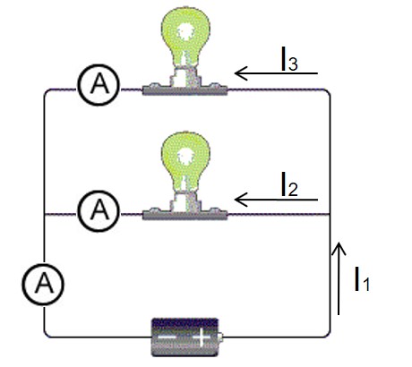
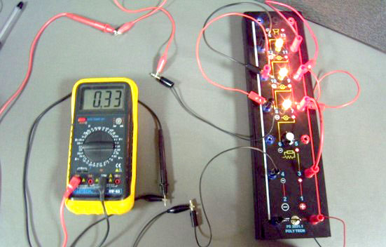
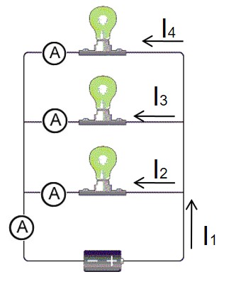
Measurements from various locations of the circuits (I1, I2, I3, I4) are different now.
Kirchhoff’s first law states that the total current entering a node in a circuit is the same as the total current leaving it. A node is defined as a point where a circuit splits into two or more paths.
Consider the current measurements recorded for your parallel circuits. Comment on how well your results support Kirchhoff’s first law.
As we see from our measurements the electric current in parallel connections is greater than that of in series. Why is that? Consider the resistance of two lamps to be R1 and R2.
The total resistance of our circuit is
So (R) is fairly reduced compared with series circuits, and as a result we see an increase in ampers.
Question 1
What is the difference between the wiring of the voltmeter and the wiring of the ammeter?
- There is no difference in the wiring of the ammeter with the voltmeter. They are connected depending on the type of circuit and the way of thinking of the researcher.
- The voltmeter is connected in series in the circuit at the point we want to measure. The ammeter in parallel (we interrupt the circuit and interpolate it) in the circuit at the measuring point.
- The voltmeter is connected in parallel in the circuit at the point we want to measure. The ammeter in series (we interrupt the circuit and interpolate it) in the circuit at the measuring point.
Question 2
An ammeter connected in series with a resistor circuit has indication equal to:
- the potential difference across the resistor.
- the intensity of current flowing through the resistor.
- the electric charge passing through the resistor.
- the potential difference across the resistor.
- the power consumed in the resistor.
Question 3
Which of the following instruments we need to calculate the load that passes in a period from a cross-section of a current carrying conductor?
- Watch
- Ammeter and watch
- Ammeter
- Tachograph
Question 4
The internal resistance of the ammeter must be sufficiently large.
- True
- False
Experiment 3/3: Voltmeter – Voltage Measurement of Electric Current
Kirchhoff’s second law
Equipment
- PS2031.1 Electric board 1
- PS2013.3 Battery holder variable
- PT2013.10 Banana and aligator clips cables
- PCB1001.25 Digital multimeter
- PS2031.5 Mini lamps x 3
Materials
- 4 batteries C type (1.5 V each)
Safety Note
There are no special safety requirements for this experiment.
In this experiment we are going to measure the potential difference across circuits both serial and parallel. In order to do that we will use a digital multimeter. Make sure that is set for direct current of up to 20 V.
In a circuit a voltmeter is always positioned in parallel to take measurements, and it’s resistance is very high in order to leave unaffected the electric current.
To make measurements we can use alligator clips as in images where they are connected with the multimeter probes or we can put the probes directly inside the jacks if we don’t mind using both hands.
Let’s make a simple circuit with one lamp.
Action: Turn on the switch and place the probes of the multimeter at 7 and 8 positions of the board as explained earlier.
Effect: We should see our measurement at the display.
Create a circuit with two lamps and measure the potential difference in each lamp and record your results.
Repeat your measurements with 3 lamps in serial too. Notice also how the glowing has been reduced with every lamp addition.
The sum of voltages of each lamp should be equal to the voltage our batteries give to the circuit V = V1 + V2 + V3.
We know that the electric current is constant for all the circuit, so how we determine the voltage of each lamp (or resistor) using Ohm’s law?
Let V1 and R1 be the voltage and the resistance for the first lamp, and V2, V3, R2, R3 for the second and third. Then it is:
V1 = I * R1
V2 = I * R2
V3 = I * R3
If we put V1, V2, V3 and R1, R2, R3 in a graph we will see they have a linear relationship.
Action: Try to disconnect the third lamp removing a clip lead, measure again the potential difference in every lamp and record your results.
Effect: This break simulated a lamp in the circuit being blown, as a result all the lamps stopped glowing.
Now on to the parallel circuits.
Create a circuit with two lamps as in image. Use the multimeter as usual to measure the potential difference of each lamp and record your results.


If we compare our results with those from the serial circuits we can see that the parallel setup is better as the voltages in each lamp are as high as the batteries provide, this is also apparent in the illumination of the lamps.
Action: Try to disconnect the third lamp removing a clip lead, measure again the potential difference in every lamp and record your results.
Effect: As we can see lamp 1 and 3 are working just fine, by disconnecting the 2nd lamp in the circuit only that particular lamp stopped illuminating. This is a clear advantage over circuits in series.
Question 1
The potential difference across the segment (A, B) of an electric circuit with current flowing is equal to:
- the charge passes from a section of the segment at a time unit
- the force exerted per unit charge
- the per unit charge transferred energy
- the per unit time transferred energy
Question 2
The voltmeter must have high internal resistance
- True
- False
Question 3
The deflection of the pointer of the voltmeter ………….. from the intensity of the current flowing through it.
- does not depend
- depends
Question 4
The components connected in series, the current flows through them have ……… voltage while those connected in parallel the current flows through them have ……… voltage.
- same/different
- different/same
- same in both cases
- different in both cases
Study of the Characteristic Curve of DC Source
Equipment
- PT2013.1 Electric board 1
- PT2013.2 Electric board 2
- PT2013.3 Battery holder
- PT2013.10 Banana cables (6 pcs)
- PTC.AC Power Supply Cables
- RS102 Current sensor
- RS101 Voltage sensor
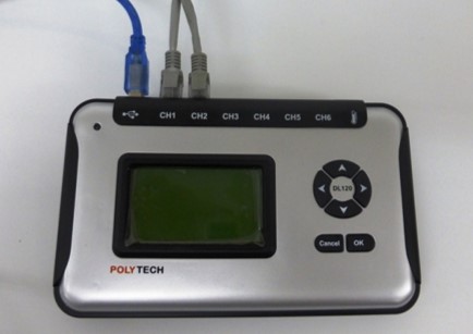
- DL120RS Data Logger
Materials
- 4 batteries C type (1.5 V each)
Safety Note
- There are no special safety requirements for this experiment.
- For the proper usage of the sensor please read the instructions manual before using it
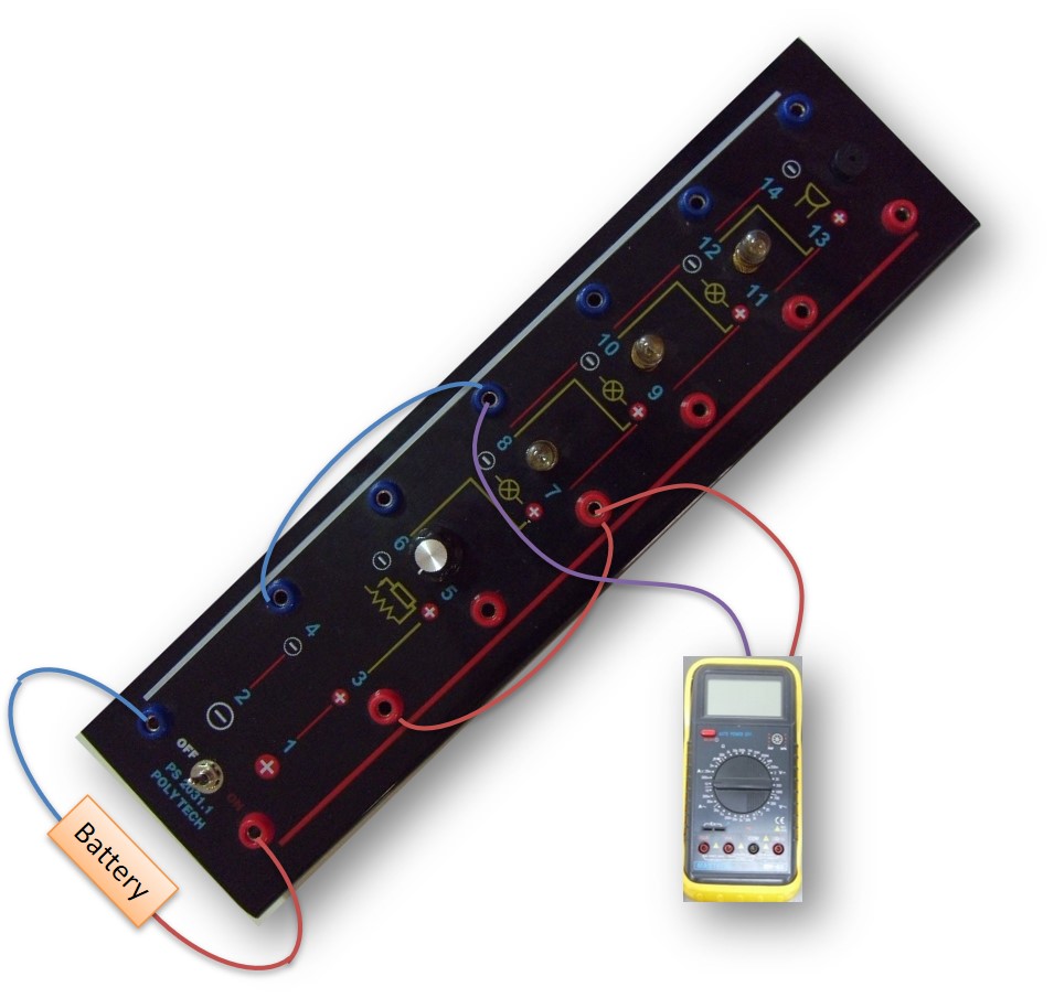
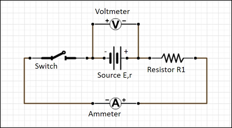
1. Create the circuit in the picture below which contains the resistor (R1) of the electric board 2, a current sensor connected in series and a voltage sensor connected in parallel with the source.

2. Connect the data logger DL120RS to the PC via USB port and the voltage and current sensors to the Data logger via a UTP cable into the ports #1 and #2.
3. Run the i lab software and select “Setup“ at the main menu.

Make sure that the “DL120RS” interface is selected.

4.a. Download and open the i lab Experiment Setup file found here:
4.a.1. Jump to step 14
OR
4.b. Select “Start” at the i lab main menu. It will open the experiment screen.

5. At the experiment screen you can see the following areas:

6. At the operating bar click «New Folder»

7. Then from the window “Select display mode” select Custom template (bottom right).
8. On the left of the screen appears an options bar. Select “View diagram” and twice consecutively “Show meter”. Each selection populates a new form window on the Experiment area.

9. Reorder and rename (by right-clicking the title) the windows properly, as shown in the image below.
10. At the Voltage-Current Diagram window, click the “Add curve” button.

11. At the new window that appears (Curve editor) we can edit the curves that will be displayed in the Diagram form.
Fill in the fields as in the picture below so that voltage is displayed at the x axis and current at the y axis.
Finally, click on the “Add” button.
12. Right-click inside the Voltage Meter Display window and select the voltage variable in V.

13. Repeat the same for the second measurement window and select current. The final forms will be as follows:

14. Everything is now ready, close the circuit and make the first measurement by pressing the “manual measurement” button.

15. Then open the circuit, disconnect the resistor R1 and connect the resistor R2. Close the circuit and press the “manual measurement” button again for the second measurement.
Repeat the same procedure for the resistors R3 and R4 and click “Stop“.


The curve is expressed by a straight line type y = ax + b where a = -r b = E. The inclination of the curve depends on the constant a that is the internal resistance of the source.
When the source has no current, the electromotive force E is equal to the voltage Vp at the poles of the source.
The physical significance of the point of curve intersection with the current axis is the maximum current that can flow through the source which is called short circuit current.
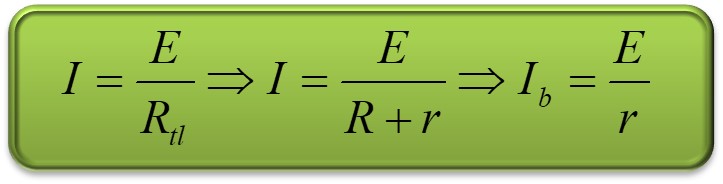
If you connect the poles of the source with a conductor of negligible resistance, ie R=0, then we say that the source is short circuited. Using Ohm’s Law:
16. Create the circuit in the following picture which contains a battery, the resistor (R1) of the electric board 2, a current sensor connected in series and a voltage sensor connected in parallel with the resistor.


17. Close the circuit and make the first measurement by pressing the “manual measurement” button.
18. Then open the circuit, connect the source to a battery, close the circuit again and press the “manual measurement” button for the next measure ment
Repeat the same procedure procedure putting three and four batteries respectively then click “Stop“.

The curve is expressed by a straight line type y = ax. So, it obeys Ohm’s law where:


The slope of the line expresses the value

If the graph was I = f(V) then the physical meaning of the curve inclination would be

Question 1
At the ends of a copper wire, of constant temperature, we apply voltage V. If we double the voltage,
- the current will be doubled
- the resistance of the wire will be doubled
- both the current and the resistance of the wire will be doubled
- the resistance of the wire will be halved
Question 2
The following graphs are characteristic curves of four different dipoles. Ohm’s Law

- applies to all four dipoles
- applies only to the dipole whose characteristic is the (2)
- applies only to the dipole whose characteristic is the (1)
- doesn’t apply to any of these dipoles
Question 3
Given the following relationships
i) V=I/R, ii) P=I2Rt, iii) W = V2Rt, iv) P = V2/R
For the resistor with resistance R apply
- the relationships (i) and (ii)
- the relationships (i),(ii) and (iii)
- the relationship (iv)
- all previous relationships
Question 4
The characteristic curve of a source is shown in the image below.

The point A of the curve intersection with the axis of the polar voltage V of the battery expresses
- the electromotive force E of the source
- the internal resistance of the source
- the value of the short-circuit current
- the power of the source
Question 5
In a closed circuit with a source (E, r) and a resistor R, the polar voltage source is smaller than
the electromotive force.
- True
- False
Question 6
In a circuit with a source and a resistor, the connection of the voltmeter across the resistor results in the alteration of the size we want to measure. Therefore the voltmeter should has a high resistance in relation to the resistance of the resistor.
- True
- False
Question 7
The LED is a:
- forward biased P-N contact
- reverse biased P-N contact
- forward polarized photomultiplier
- reverse biased photomultiplier